by Arthur Brown and James Colvin
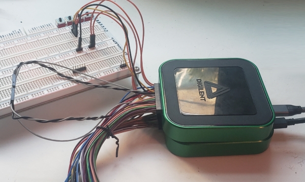
Dual Mode is a newly introduced feature of WaveForms that came out when the Analog Discovery 3 launched. It allows you to connect two of the same kind of Mixed Signal Oscilloscope together and synchronize their acquisitions so that you can double the channel count of your acquisition system. It is supported for analog inputs, analog outputs, and digital inputs and outputs.
Note that this feature has been implemented for many of our mixed signal oscilloscopes, including the Analog Discovery Pro 3000-Series – Two Analog Discovery Pro ADP3450 can be connected to create an 8-channel scope system!
This article will demonstrate how to set up Dual Mode with a pair of AD3’s and how to configure the system to account for clock delay.
Hardware Setup
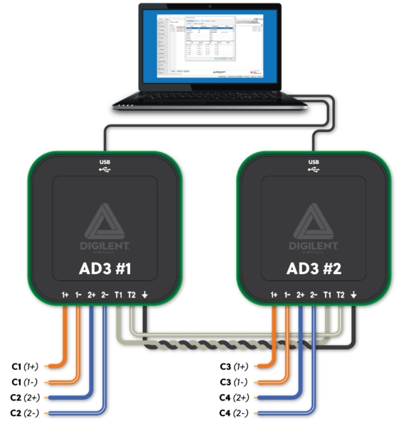
To use Dual Mode, you need to connect the external trigger pins of the two devices. Connect T1 to T1 and T2 to T2. The T1 signal will be used to pass a reference clock between the devices, which ensures that they use the same clock source. T2 will be used to pass the selected trigger source between devices so that they start their acquisitions at the same time. Their grounds should be connected to minimize crosstalk. Additional reduction in crosstalk can be achieved by using a twisted wire pair for the T1 reference clock signal. With MTE cables, you can twist a ground wire together with the clock. For best performance, keep the cables as short as possible.
WaveForms Software Setup
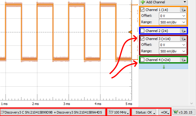
Select the first device that you want to be the host device. Click the “Select + Dual” option and choose the second identical device. Follow the listed instructions of connecting Trigger and Ground pin between the two devices. Within the Scope instrument, you’ll now see the secondary set of analog inputs from the additional device. Take note of some other indicators along the bottom of the screen, showing which devices are selected, additional device settings, and device status.
System-dependent Phase Shift
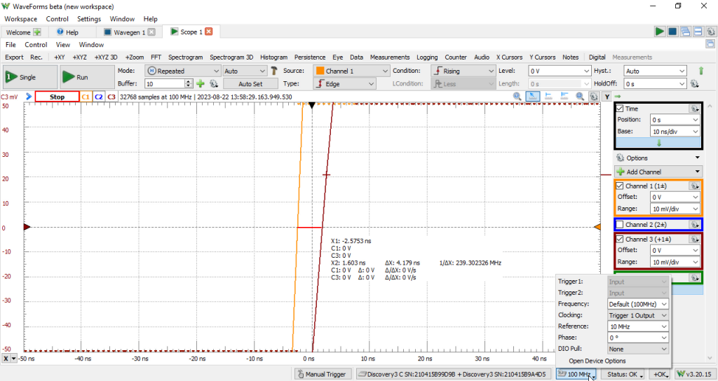
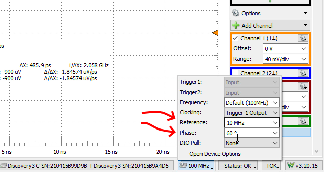
Despite the two devices now connected and sharing a reference clock and trigger line, there may still be some phase differences between the two devices due to the propagation delay of the reference clock from the primary device to the secondary device. Without any adjustment, the same signal being sent to both devices will appear to have a delay. In this case, we measure the skew by taking the difference in time between when the two captured signals cross 0 V. We can correct for that providing a phase adjustment; you can find the “Phase” setting in the Device Options dropdown (the 100 MHz button) at the bottom of the window. This lets you manually adjust the clock for the second device, so that data is sampled slightly earlier with respect to a clock edge than it is on the other device. This accounts for the propagation delay from one device to the other – because the clock arrives to the second device later than the first, the second device needs to sample earlier than the first, so that the samples are taken at approximately the same time.
To select an appropriate phase offset for the clock signals a shared signal source should be used to test out the system. You can use the same analog output channel from one device providing a stimulus signal to scope channel 1 of both devices. A square wave is well suited to be a test signal for this since it’s easier to compare when a rising edge crosses a particular threshold than it is to compare two slowly-rising signals.
Phase Adjustment
Next, we’ll start adjusting the phase offset between the two devices. Zoom in to a very narrow timebase and have only one channel from each device enabled on the view plot.
With a trigger condition set for the primary device (such as the trigger for when Channel 1 crosses the 0 V value), you’ll be able to see how many nanoseconds before or after the receiving channel on the secondary device crosses that same threshold.
Adjust the Phase dropdown from the Device Options and see if the signals from the two devices are now crossing the set threshold at nearly the same time; continue adjusting the phase until you are satisfied with the results.
Also, take note of the reference clock option – it allows you to change the frequency of the clock passed over the T1 trigger line, which is then used to generate the system clock of the other board. Different values may perform better or worse depending on your application.
As you experiment, don’t forget that you can adjust the ranges of the channels. This can help spread the signal more vertically across the plot and make it easier to discern where the zero crossings are.
You’ve seen what can be considered a bad phase offset, earlier in this article. So, let’s look at what we can easily obtain after some experimentation. At least for our setup, we got the offset down to 247.7 ps out of a 10 ns clock period (100 MHz clock), 10x better than what we got with default settings.
For more of a visual on this process, check out this short video clip:
The Analog Discovery 3 is available from stock at Elfa Distrelec A/S, the authorized distributor of Digilent in Denmark.

